Lab 3 - ToF
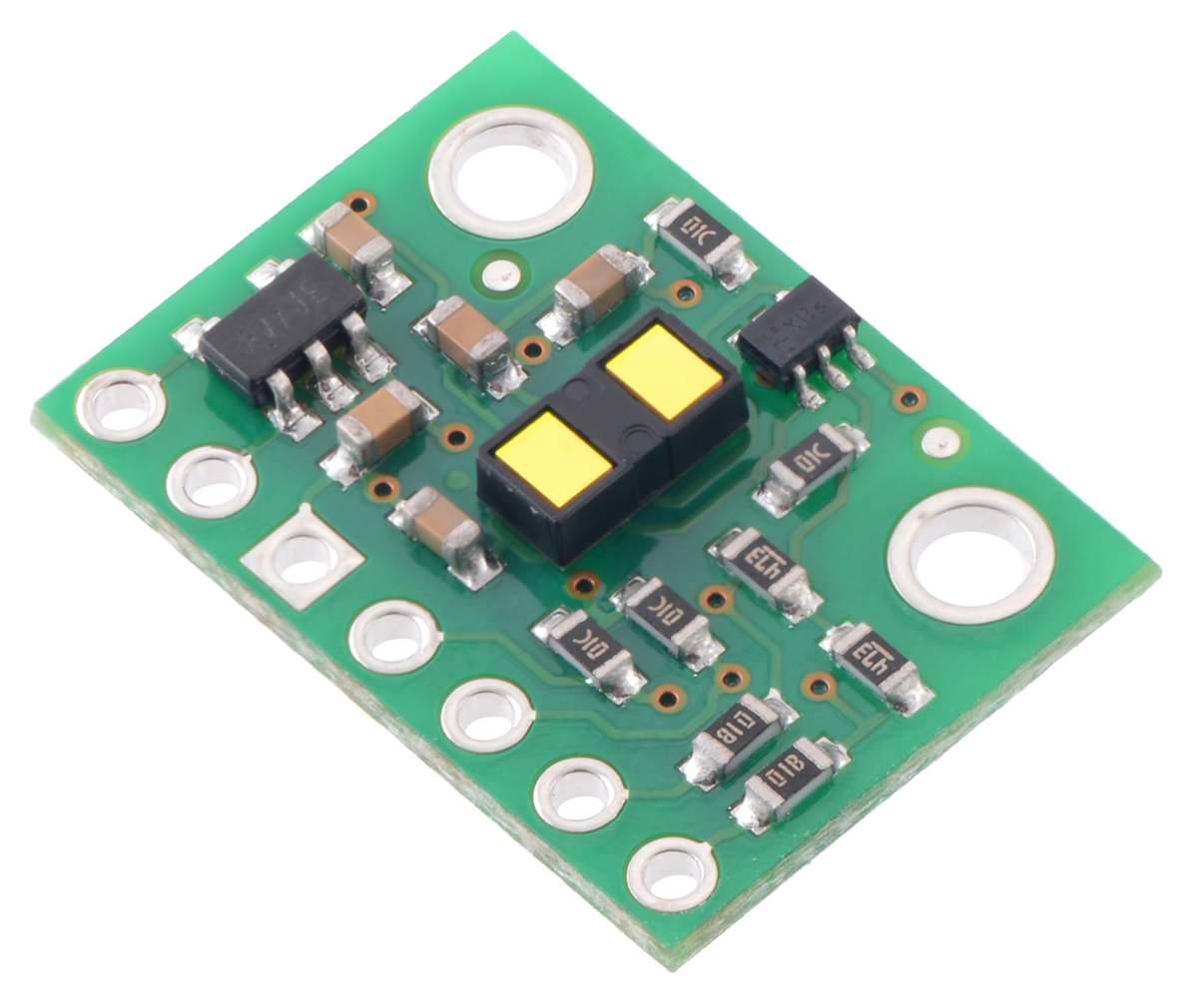
The objective of Lab 3 is to learn how to use the Time of Flight sensor; and being able to use two of them in parallel.
Prelab
Before the lab, the Time of Flight (ToF) manual and datasheet were read.
In this lab we will use two ToF sensors (sensor A and B). However, they share the same I2C address (0x52), so we won’t be able to communicate with each other separately. We will need to change the I2C address of one of those sensors, so we can treat them as two different components. To achieve this we should:
- Connect sensor A XSHUT pin to a GPIO pin in the Artemis (I will connect it to PIN 8).
- Toggle the XSHUT pin LOW to turn off sensor A.
- Change the address of sensor B with the command
distanceSensorB.setI2CAddress(NEW_I2C_ADDRESS);. - Toggle the XSHUT pin HIGH to turn on sensor A again.
Now we can send specific commands to each sensor. Next, let’s discuss the placement of the sensors inside the robot. One of them will be at the front of the car to determine the distance to an obstacle. The second sensor can be in either side of the robot or in the back. I will place mine in one of the sides, so we map locations more efectively, as well as being able to perform tasks such as maintaining a certain distance from the wall.
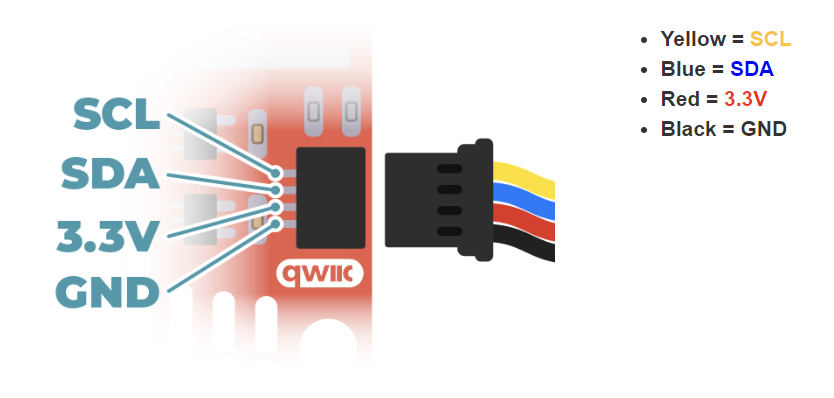
To achieve more flexibility, I will use the long Qwiic cables for the ToF sensors, so I can place them anywhere in the robot. The IMU will be connected through a short Qwiic cable, as it can be in the middle of the robot. All of these sensors will be connected to the Artemis through a breakout board. The Qwiic cable for the ToFs needs to be soldered. The connection will follow the Qwiic color convention, as shown in this picture from the Sparkfun website.
The wiring will look as follows.

Tasks
1. ToF connection
The ToF sensors were connected as described above to the Artemis.

2. I2C Address Scan
Running the example from File->Examples->Apollo3->Example05_Wire_I2C we can check the address of a component. We will start with one ToF. The address displayed is 0x29 (and not 0x52). According to the datasheet, the ToF uses the last bit to specify the data direction (read/write). The example file ignores the last bit.

We can use this code to check the IMU address as well, which is the same provided in its datasheet.

3. Parallel Sensors and Distance Mode
From now on, I will use two ToF sensors in parallel. We can use both at the same time as explained in the Prelab. Using distanceSensorA.getI2CAddress() we can obtain the address of each sensor and check that each has their own address.

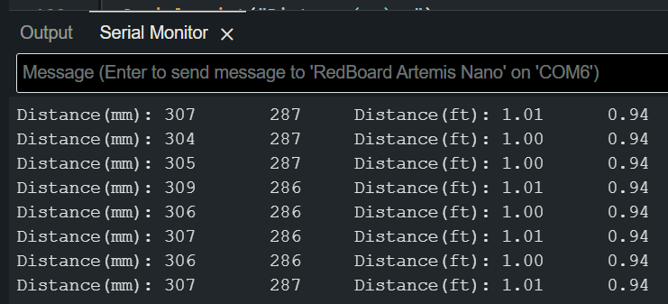
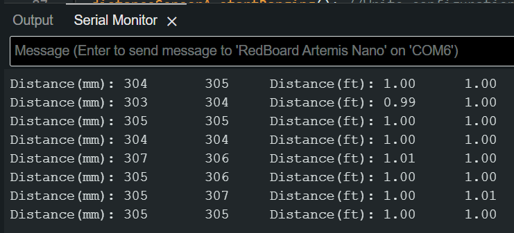
We can use the example from File->Examples->SparkFun_VL53L1X_4m_Laser_Distance_Sensor->Example1_ReadDistance to read different distances from the ToF. I modified the example to use two ToF as explained before. When placed at the same distance of an object, the two sensors read different distances. One of the sensors had correct readings; however, the other had a slight offset. This can be fixed placing the sensor at a know distance from the object and using the function distanceSensorA.calibrateOffset(304.8);. In my case, as I only have a ft/inch measuring tape, I placed both my sensors 1ft (304.8mm) from the object, and obtained the offset. For sensor A, the offset was 0. However, for sensor B the offset obtained after 5 calibration was 21mm. Once we know the offset we can use distanceSensorB.setOffset(21); to define the offset without the need to calibrate the sensor every time.
| Before calibration | After calibration |
 |
 |
Next, the ToF sensors have two different modes: Short, more precise but only works up to 1.3m; and Long (default), with less precision, but reaches 4m. To check which one to use, I will set sensor A to work in Short mode, and sensor B to work in Long mode, and compare how the readings differ at different distances.
1
2
distanceSensorA.setDistanceModeShort();
distanceSensorB.setDistanceModeLong();

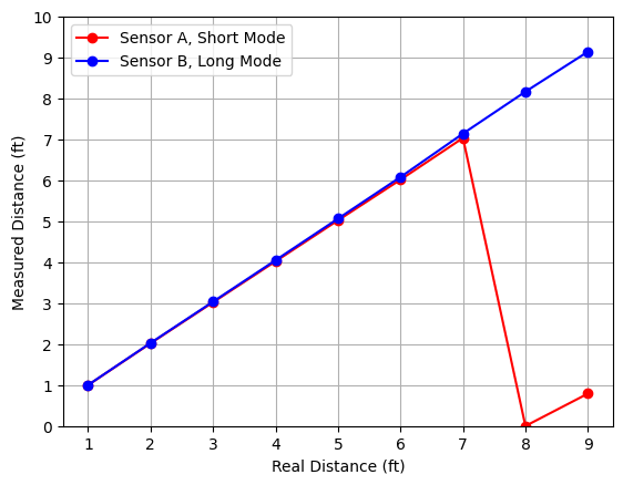
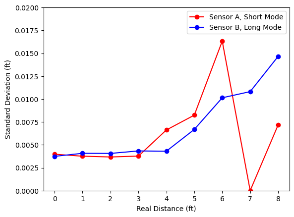
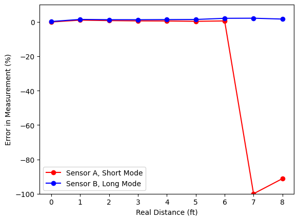
I gathered 100 readings every 1ft from 1ft (0.304m) to 9ft (2.74m). To measure and send the data over Bluetooth, I will use the same method as described in Lab 2, so that the code execution is as fast as possible. The functionality to initialize both ToF sensors and read data was ported from the previous example to the ble_arduino file. The average reading at each distance, standard deviation and relative error is shown below.
 |
 |
 |
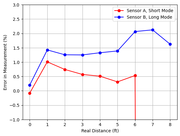 |
The first outcome is that sensor A (short mode) is able to obtain accurate readings up to 7ft (2.1m), which surpases the theorical limit of that mode. Additionally, sensor B (long mode) can obtain accurate results even at short distances: the difference in error between short and long mode is less than 1%. We can also see that the error and the variability of the measurements (standard deviation) increase as the distance increases. However, they are still low compared with the distance measured. Based on this information, I will use both sensors in Long mode, as the accuracy increase in Short mode is not worth the loss of range.
4. Sensor speed
To test the speed of the sensors, I will modify the Example1_ReadDistance file so that it displays the time at every iteration, and only print the distance if there’s new data ready. We can see that the limiting factor is the ToF reading speed, and not he Artemis clock speed.
1
2
3
4
5
6
7
8
9
10
11
12
13
14
15
16
17
if (distanceSensorA.checkForDataReady()){
  int distanceA = distanceSensorA.getDistance();
  distanceSensorA.clearInterrupt();
  distanceSensorA.stopRanging();

  Serial.print("Distance A(mm): ");
  Serial.println(distanceA);
}
if (distanceSensorB.checkForDataReady()){
  int distanceB = distanceSensorB.getDistance();
  distanceSensorB.clearInterrupt();
  distanceSensorB.stopRanging();

  Serial.print("Distance B(mm): ");
  Serial.println(distanceB);
}
Serial.println(millis());
5. Time vs Distance
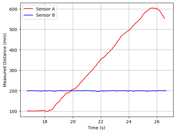
Last, I will collect 100 readings from both sensors at different times, and send them over Bluetooth. Sensor A is kept at a fixed distance, while the distance for sensor B varies.
