Lab 4 - Motors

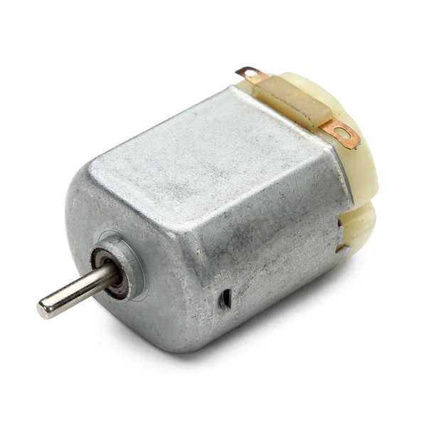
The objective of Lab 4 is to learn how to use the motors on the robot, with one driver for each motor.
Prelab
In this lab we will use a dual motor driver for each motor. A single driver cannot output the necessary current to drive one motor. However, as there are two drivers in each IC, we can use both for a single motor, delivering the desired current.
In order to run the car for longer, and have enough current for all the robot, we will use two different batteries: a 650mAh battery to power the Artemis and other sensors; and a 850mAh battery to drive the motors. In this case, the motors may require a high current to turn on, but the rest of the robot will still work properly. Even though there are different power sources, the whole robot shares the same ground.
I will connect the right motor to PIN 11 (forward) and PIN 12 (backwards); and the left motor to PIN 5 (forward) and PIN 6 (backwards). Note that PIN 12 will be changed, as later explained.

Tasks
1. Motor Drivers Testing
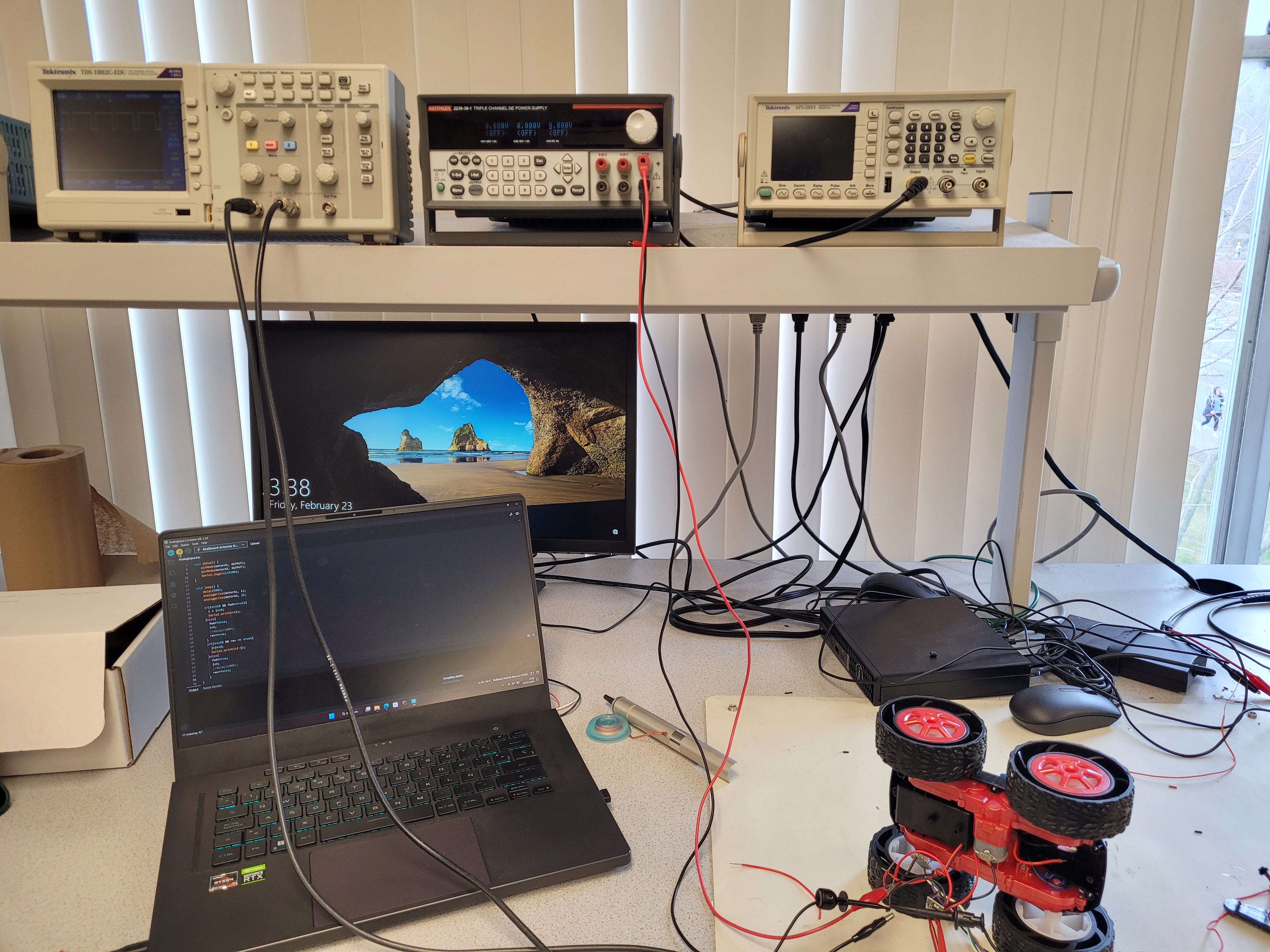
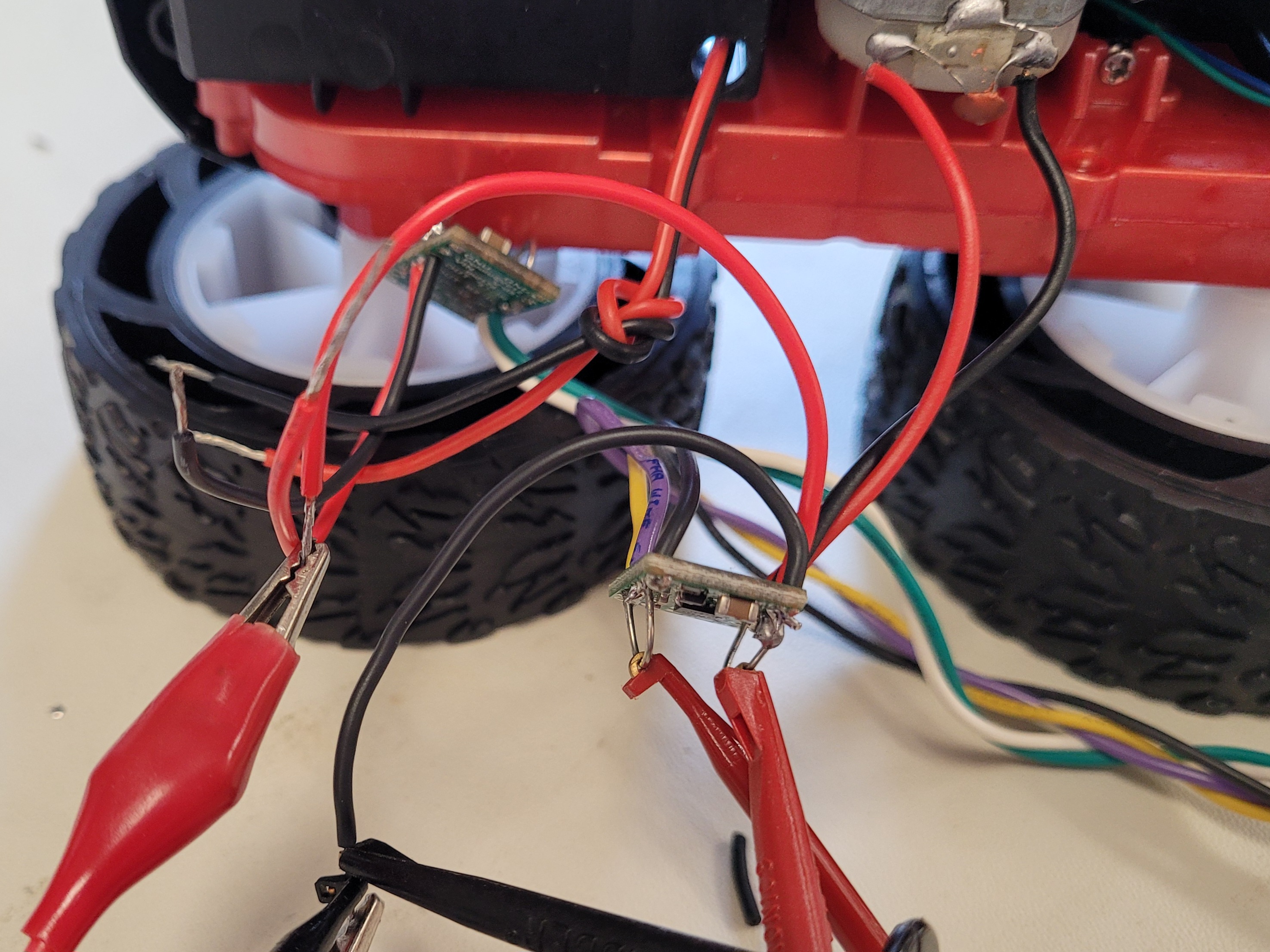
Before all the components were soldered into the car, I tested each motor driver individually. I powered them with an external 3.7V power supply (same voltage as the battery we are going to use). I also connected the driver input and output PINs to the oscilloscope, to check that the signals were correct.
 |
 |
To test the entire range of the motor, I wrote a simple piece of code that changed the speed of the motor every few seconds, and drives it both forward and backwards.
1
2
3
4
5
6
7
8
9
10
11
12
13
14
15
16
17
18
19
20
21
22
void loop(){
  analogWrite(motorA1, i);
  analogWrite(motorA2, j);

  if(i<=230 && fwd==true){
    i = i+10;
    Serial.println(i);
  }else{
    fwd=false;
    i=0;
    rev=true;
  }

  if(j<=230 && rev == true){
    j = j+10;
    Serial.println(-j);
  }else{
    fwd=true;
    j=0;
    rev=false;
  }
}
First, I tested the right motor.
Then, I tested the same configuration with the battery attached; and repeated the same experiment with the left motor.
Last, I tested both motors spinning at the same time.
We can conclude that the motors, and their drivers, work as expected (at least with the proposed testing code; we will see that not all possible scenarios work with the current configuration). Then, I hooked up every component to the chasis.

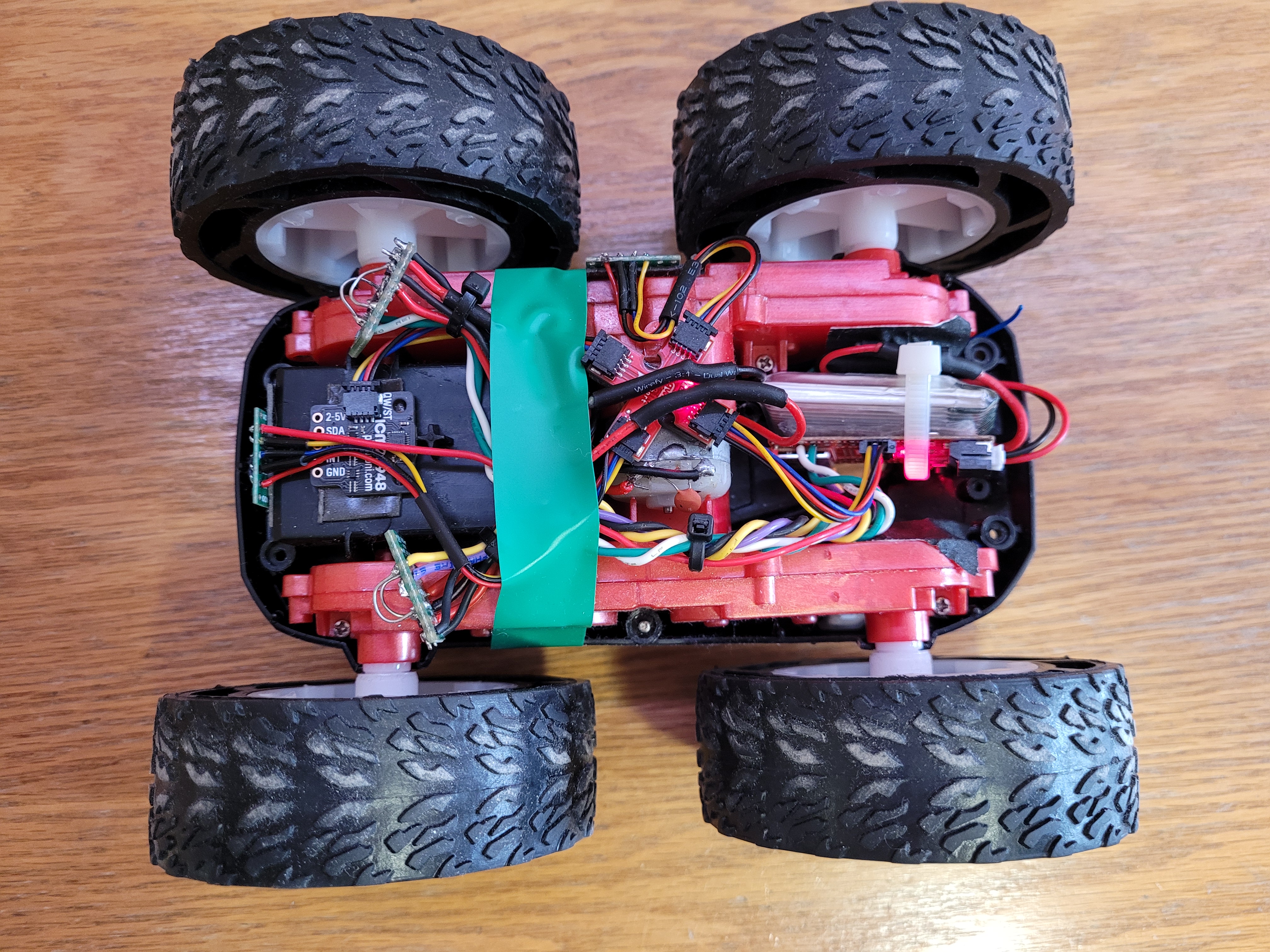
Update: After Lab 5, I had to resolder a new Artemis as the voltage regulator was broken. The new layout of the robot is as follows:

2. Lower PWM limit
From the previous experiments, we can see that the motors didn’t turn on right at the beginning. Rather, they needed a certain PWM value to beat friction and start moving. A function was created in Arduino that receives values for the speed of both motors from Bluetooth. This way, it is easier to test the lower threshold of PWM needed for each wheel to spin. After some trial and error I arrived at the following values (rounded to the higher tenth as a safety measure) for the lower limit of PWM needed so that the wheels can spin on the floor.
| Wheel | Forward | Backwards | ||
| Right | 80 | -80 | ||
| Left | 80 | -80 | ||
| Both | 60 | -50 |
Note how a single wheel needs more power to start spinning; while with both doing the job, each require less power. Knowing this, we can map the speed so that an input of 100 corresponds to full speed, an input of 1 corresponds to the lower PWM limit found, and 0 corresponds to no movement.
1
2
3
4
5
6
7
8
9
10
11
12
13
14
15
16
17
18
19
20
21
22
void setSpeed(int speed_R, int speed_L){
  int rawSpeed_R;
  int rawSpeed_L;

  if(speed_R == 0){
    rawSpeed_R = 0;
  }else if(speed_R > 0){
    rawSpeed_R = motorR.lower_limit + (speed_R/100)*(255 - motorR.lower_limit);
  }else{
    rawSpeed_R = -motorR.lower_limit + (speed_R/100)*(255 - motorR.lower_limit);
  }

  if(speed_L == 0){
    rawSpeed_L = 0;
  }else if(speed_L > 0){
    rawSpeed_L = motorL.lower_limit + (speed_L/100)*(255 - motorL.lower_limit);
  }else{
    rawSpeed_L = -motorL.lower_limit + (speed_L/100)*(255 - motorL.lower_limit);
  }

  setMotorSpeed(rawSpeed_R, rawSpeed_L);
}
3. Motor Calibration
The next step is ensuring the robot can drive in a straight line, both forward and backwards.
Without Calibration:
We can see that, without calibration, the robot tends to turn left. Therefore, I developed a small piece of code that receives from Bluetooth some calibration factors, and applies them to the motors at full speed. With trial and error I obtained that the calibration factor for the left motor going forward should be 1.0355; while going backwards it should be 1.005. The right motor doesn’t need any factor, as it is slower that its counterpart. By introducing calibration we are making both speeds the same.
1
2
3
4
5
6
7
8
9
10
11
12
13
14
15
16
17
void setMotorSpeed(int speed_R, int speed_L){
  if(speed_R > 0){
    analogWrite(MOTOR_R_FWD, speed_R/motorR.calibrationFWD);
    analogWrite(MOTOR_R_BACK, 0);
  }else{
    analogWrite(MOTOR_R_FWD, 0);
    analogWrite(MOTOR_R_BACK, -speed_R/motorR.calibrationBACK);
  }

  if(speed_L > 0){
    analogWrite(MOTOR_L_FWD, speed_L/motorL.calibrationFWD);
    analogWrite(MOTOR_L_BACK, 0);
  }else{
    analogWrite(MOTOR_L_FWD, 0);
    analogWrite(MOTOR_L_BACK, -speed_L/motorR.calibrationBACK);
  }
}
With Calibration:
4. Open Loop
Last, to test the entire functionality of the robots, a small open loop program was created: run forwar, turn, run forward, stop, run backwards.
1
2
3
4
5
6
7
8
9
10
11
12
void openLoopTest(void){
  setSpeed(80, 80);       //Forward
  delay(1200);
  setSpeed(70, -70);      //Turn
  delay(500);
  setSpeed(60, 60);       //Forward
  delay(1000);
  brake();                //Stop
  setSpeed(-20,-20);      //Backwards
  delay(1000);
  brake();                //Stop
}
When testing, I noticed that the robot didn’t turn as expected. After some debugging I noticed that PIN 12 didn’t output any current unless the left backwards PIN also output some current. After changing it to PIN 13, everything worked as expected.
A video of the open loop control is shown below.
Note: As you may have noticed, some videos have a cable connected to the robot. This is because, when recording those videos, the battery powering the Artemis broke down, so I needed to power the board from an external source. This didn’t have any major impacts in the robot behaviour.