Lab 5 - Position Control

The objective of Lab 5 is to develop a PID controller so that the robot runs towards a wall and stops at 1ft.
Prelab
As part of this Prelab, we have to setup a debugging system with Python and Bluetooth. First, I will create a command, PID_TEST, that will run the Position Control code, while storing data for debugging. It will stop when the data arrays are full. The size of these arrays can be changed with a macro.
The PID_TEST command will receive 5 arguments: whether I want to use extrapolation or not, the Set Point to the wall, Kp, Ki and Kd. Being able to change these parameters quickly over Bluetooth will help us later when tuning the PID controller.
Python command:
1
ble.send_command(CMD.PID_TEST,"1|305|0.1|0|0") #This means: use extrapolation, setPoint=305mm, Kp=0.1, Ki=Kd=0
Arduino code:
Case definition:
1
2
3
4
5
6
7
8
9
10
11
12
13
14
15
16
17
18
19
20
21
22
23
24
25
26
27
28
29
30
case PID_TEST:{
  /*
    Collect all the arguments with:

    success = robot_cmd.get_next_value({variable_name});
    if(!success){
      return;
    }

    ...
  */


  /*
    Enable ranging in the TOF sensor
  */
  distanceSensorA.startRanging();

  /*
    Initialize all necessary variables...
  */

  /*
    Start the test
  */
  pid.run_test = true;

  Serial.println("Test started.");
  break;
}
Storing variables:
1
2
3
4
5
6
7
8
9
10
11
12
13
14
15
16
17
18
19
20
21
22
23
/*
  Inside the loop
*/
  if(pid.run_test){
    /*
      PID controller code...
    */

    //Store variables used to debug
    pid.distance[pid.i] = pid.curr_distance;
    pid.time[pid.i] = pid.curr_time;
    pid.pid_val[pid.i] = pid.pid;
    pid.pid_error[pid.i] = pid.error;
    pid.i++;

    //If I run out of space, end test
    if(pid.i >= N_PID){
      pid.run_test = false;
      pid.pid = 0;
      brake();
      Serial.println("Test ended. Brake");
    }
  }
The second command is SEND_DATA_PID, which will tell the Artemis to send all its stored debugging data to the computer. In Python, there’s a notification handler that parses all the data. This command has the same functionality as in previous labs.
Tasks
1. P/I/D Controller Type
The PID controller has three terms:
- The Proportional control is just a proportional gain over the error.
- The Integral control remembers previous errors so that we can achieve 0 error.
- The Derivative control determines future errors to anticipate and get quicker to the desired state.
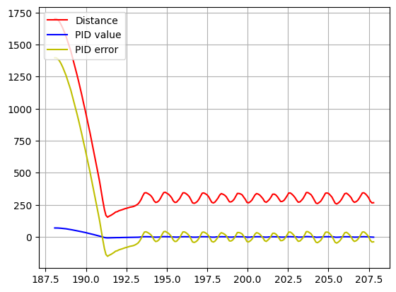
To determine the type of controller, I will run a test with a simple P controller. I run a test with Kp = 0.05. We can see that the robot oscillates around 0 error when it reaches the end. This means that we need a derivative control to eliminate those oscillations and make changes to the PID quicker. However, an integral control is not needed, as the error we get is already 0.
2. Controller Implementation
Even though I’m not using integral action, I will implement it for future ocassions (and now set Ki to 0). My controlling variable is pid.pid, which is also the value I input to the motor. The PID value can be between 0 and 1, meaning that some movement is still required. As the motor only accepts integers, I will round up those values to 1. Then, I will set the speed with the function created in Lab 4, which converts inputs so that an input of 1 is the value of the deadband, and 100 corresponds to 255.
1
2
3
4
5
6
7
8
9
10
//If the PID is less than 1, but not 0, round up to 1, as the PWM only accepts integers
if(abs(pid.pid) < 1 && abs(pid.pid) > 0){
  if(pid.pid > 0){
    setSpeed(1, 1);
  }else{
    setSpeed(-1, -1);
  }
}else{
  setSpeed(pid.pid, pid.pid);
}
Additionally, as the maximum speed input is 100, I will limit the PID value to +-100.
1
2
3
4
5
6
7
//Limit the PID to a certain speed (#define MAX_PID 100 previously)
if(pid.pid > MAX_PID){
  pid.pid = MAX_PID;
}else if(pid.pid < -MAX_PID){
  pid.pid = -MAX_PID;
}
I will define the error so that if we are further than the Set Point, the pid input to the motor will be positive and the robot will go forwards. I will also consider small errors (less than 5mm) equivalent to 0.
1
2
3
4
5
6
7
8
9
10
11
//Obtain error and dt
pid.error = pid.curr_distance - pid.setPoint;
pid.dt = pid.curr_time - pid.last_time;

//If error is too small, make it 0. It is an acceptable position
if(abs(pid.error) <= 5){
  pid.error = 0;
  pid.last_n_error_0++;     //This variable is used for extrapolation. Explained later
}else{
  pid.last_n_error_0 = 0;
}
Now, once we have a distance reading or estimation (explained in the next part), we should update the pid value. First, let’s implement the derivative term. As will be explained later, we need a Low Pass Filter to get rid of noise above 100Hz. However, we shouldn’t worry about derivative kick. Additionally, I will discard calculations of the derivative term when dt=0, as it will produce an infinite value.
1
2
3
4
5
6
7
8
9
10
11
12
13
//Apply Low Pass Filter and avoid dt=0 (infinite values for derivative)
if(pid.dt==0){
  pid.derivative = pid.prev_derivative;
}else{
  pid.raw_derivative = (pid.error - pid.prev_error)/pid.dt;
  pid.derivative_1 = pid.alpha*pid.raw_derivative;
  pid.derivative_2 = (1-pid.alpha)*pid.raw_derivative;
  pid.derivative = pid.derivative_1 + pid.derivative_2;   //I implemented the filter in two steps so that the Artemis runs it properly.
                                                          //Otherwise it runs in some problems.
}

// Update previous derivative for next iteration
pid.prev_derivative = pid.derivative;
Now, we should implement the integration term. As this term increases over time, I will implement a wind-up so that it doesn’t get above certain values.
1
2
3
4
5
6
7
if(pid.integral > 1000){
  pid.integral = 1000;
}else if(pid.integral < -1000){
  pid.integral = -1000;
}

pid.integral = pid.integral + pid.error*pid.dt;
Last, we need to update the value of the pid, with the values of Kp, Ki and Kd from Bluetooth and other terms from calculations.
1
2
3
4
5
6
//Obtain PID controller value
pid.pid = pid.Kp*pid.error + pid.Ki*pid.integral + pid.Kd*pid.derivative;

//Update parameters for future calculations
pid.prev_error = pid.error;
pid.last_time = pid.curr_time;
The code that will run the test is the following.
1
2
3
4
5
6
7
8
9
10
11
12
13
14
if(pid.run_test){

  /*
    Estimate or obtain distance...
  */

  /*
    Update PID...
  */

  /*
    Record debugging data...
  */
}
3. Ranging Time and Extrapolation
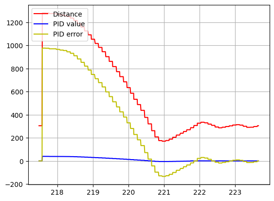
In the previous test, the updates to the PID controller were only done when a new TOF reading was available. The sensor is slow: the sampling rate is approximately 100ms. We can improve it in two ways:
-
First, if there’s no new data from the sensor, use the old one, but still update the PID controller. The results are exactly the same as before. However, the sampling rate is now roughly 7ms.
-
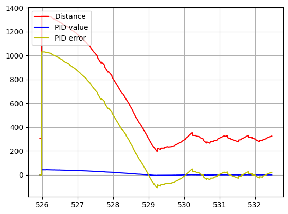
Second, when there’s no data, we will estimate it with a simple extrapolation, based on the previous two distance points. The sampling rate remains almost the same at 9ms; but now we have new values of distance every cycle. In my implementation, I won’t estimate any distance until the first sensor reading is obtained. Additionally, if the last 5 iterations indicated 0 error, I won’t estimate any new distance, as a way of filtering out possible random noise in the sensor.
We can implement the extrapolation as follows:
1
2
3
4
5
6
7
8
9
10
11
12
13
14
15
16
17
18
19
20
21
22
23
24
25
//Obtain current time
pid.curr_time = millis();

//Obtain distance data or estimate
if(distanceSensorA.checkForDataReady()){
  pid.curr_distance = distanceSensorA.getDistance();
  distanceSensorA.clearInterrupt();

  if(!pid.first_reading){
    pid.first_reading = true;
  }else{
    pid.slope = (pid.curr_distance - pid.prev_distance)/(pid.curr_time - pid.last_reading_time);
  }

  pid.last_reading_time = pid.curr_time;
  pid.prev_distance = pid.curr_distance;
}else{
  if(pid.extrapolation && pid.first_reading){
    if(pid.last_n_error_0 >= 5){
      pid.curr_distance = pid.prev_distance;
    }else{
      pid.curr_distance = pid.prev_distance + pid.slope*(pid.curr_time - pid.last_reading_time);
    }
  }
}
We can see that now we have more reliable distance data, that updates every cycle.
| Old reading data | Estimated distance |
 |
 |
4. PID Tuning
With the extrapolation, the frequency of the system is around 100Hz. I will implement a Low Pass Filter in the derivative action to get rid of any possible noise (as we can see in the second figure) above 100Hz. We don’t have to worry about derivative kick as the SetPoint is constant. Last, I will tune my PD controller using the 2nd Heuristic method from lecture (Increase Kp until oscillation, reduce, increase Kd until oscilation, reduce, iterate).
The results are shown here:
1. Kp = 0.1; Kd = 0.0

2. Kp = 0.025; Kd = 0.01 (no LPF)
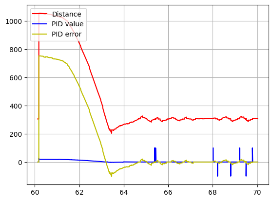
3. Kp = 0.025; Kd = 0.01 (with LPF)
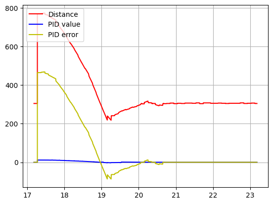
After some testing I arrived at the following values:
4. Kp = 0.07; Kd = 0.15
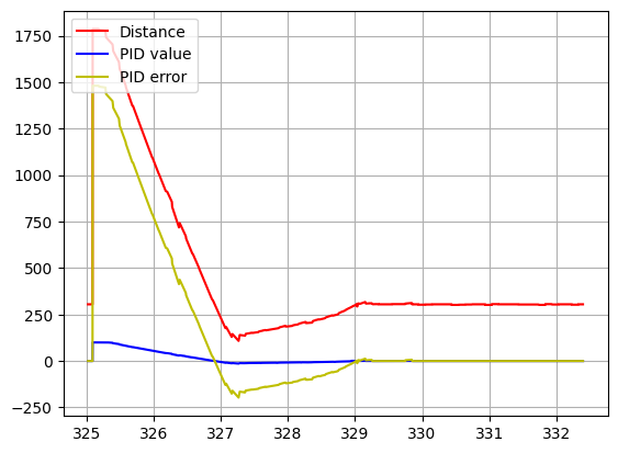
We can see the results here:
Here, the controller faces a moving wall:
NOTE: As in Lab 4, some videos have a cable connected to the robot. This is because powering the Artemis from a battery doen’t work. New batteries have been tested, so the problem is possibly related to the voltage regulator of the Artemis. In future labs I will test a different board. This didn’t have any major impacts in the robot behaviour for this lab. UPDATE (March 14th): The issue has been now resolved. The problem was caused by the Artemis board (probably the voltage regulator). After replacing the Artemis, the issue was resolved.