Lab 9 - Mapping
The objective of Lab 9 is to map a static room with the robot.
Prelab
The prelab of this lab consists of reviewing the lecture on transformation matrices, as they will be useful later on.
Tasks
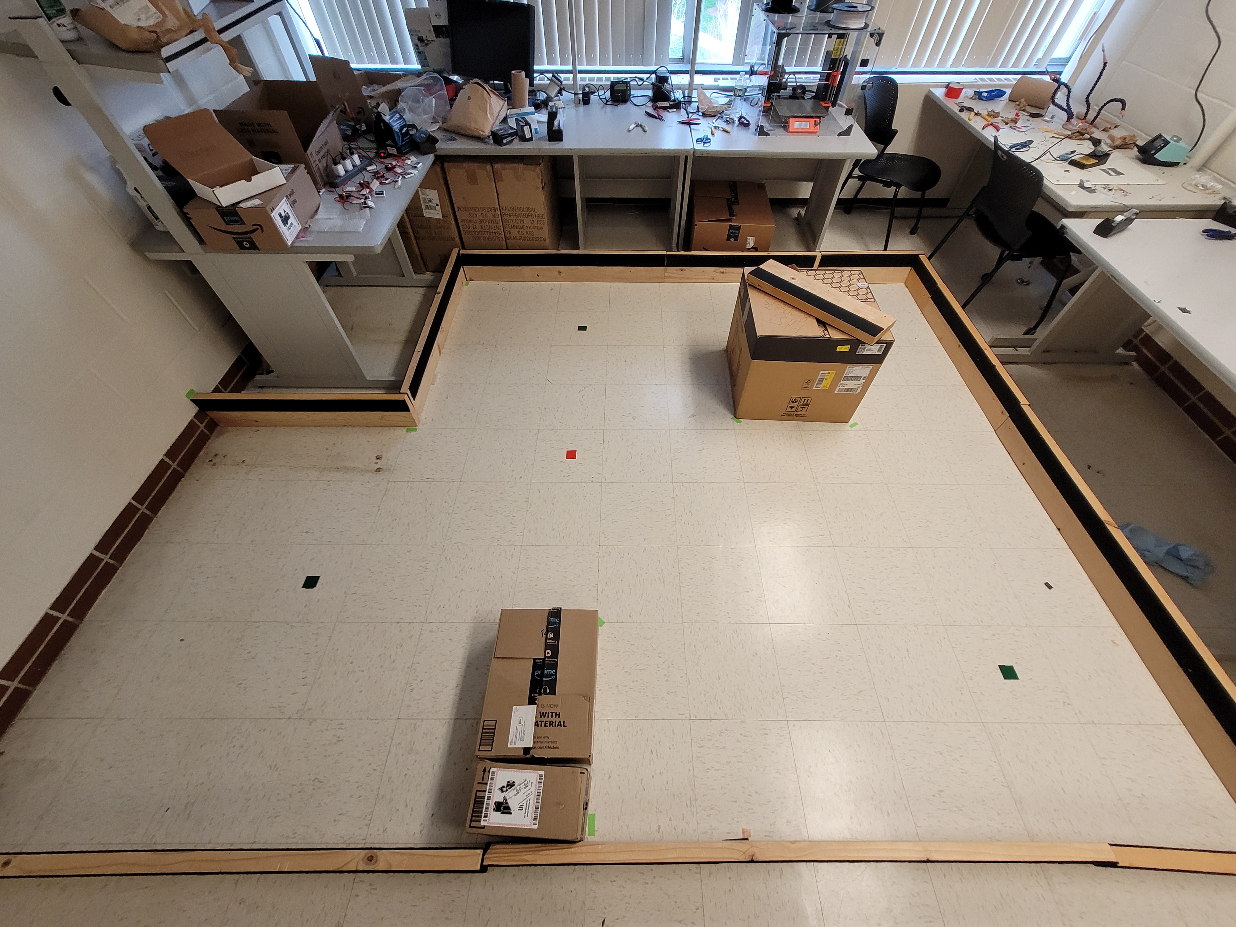
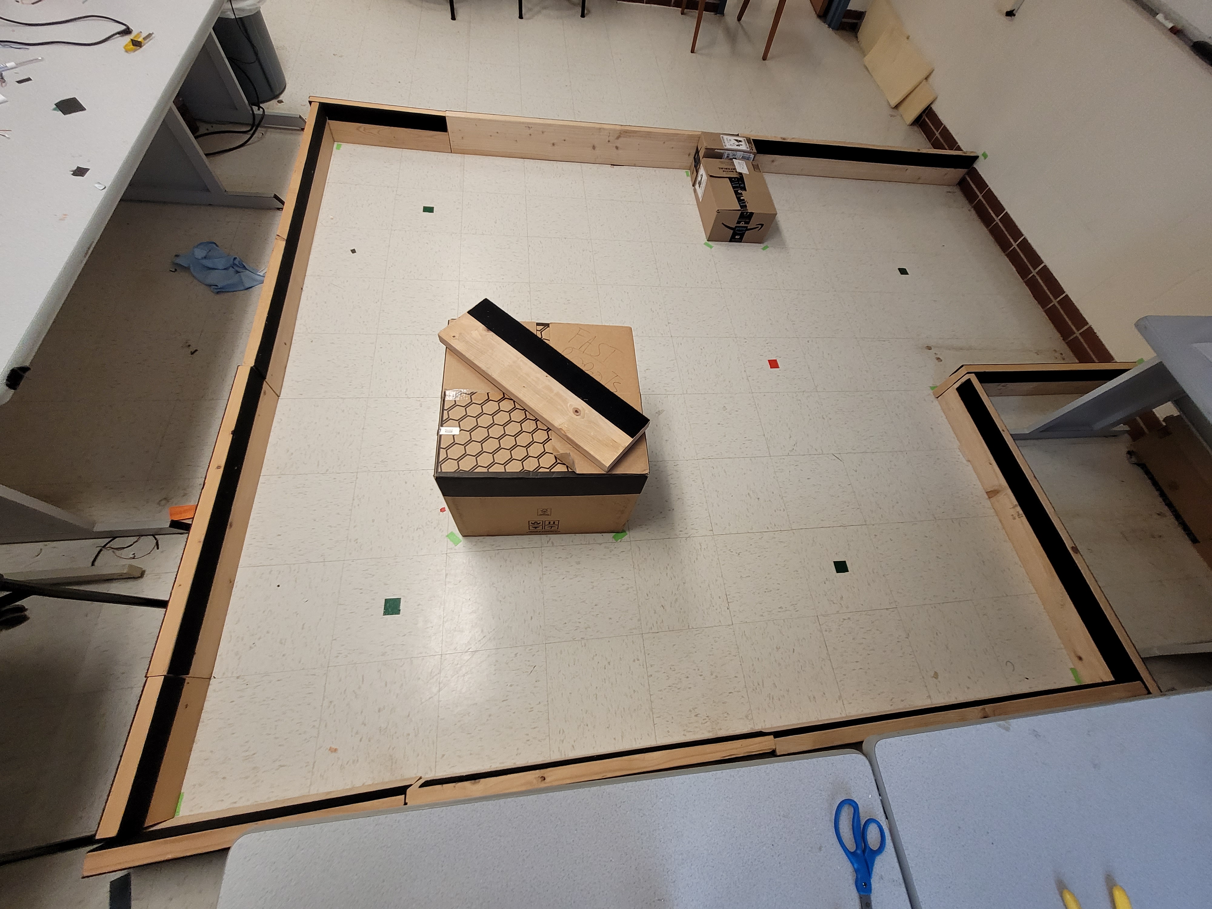
The goal of this lab is to map certain room. To do this, the robot will rotate on its axis in small angles, and obtain the distance to the wall at that angle. The way I chose to do this was with Orientation Control, as it has proven to be an efective method in previous labs. The room the robot will map is shown below. The robot will be placed at every point marked in the floor and get readings from there.
 |
 |
1. Orientation Control
The first step of the lab is to set up the Orientation Control, so that the robot reads a distance every certain angle. The Controller from Lab 6 was reused, with some modifications.
-
Aside from Kp, Ki and Kd, the number of readings (
nReadings) and the angle between each reading (angle_to_turn) were also set via Bluetooth. -
Whenever the error is 0 for some loop cycles, the controller will reset the angle back to 0 (therefore reducing the drift), read the distance to the wall, and perform a new turn.
1
2
3
4
5
6
7
8
9
10
if(mapp.last_n_error_0 >= 5){
  //Read new values from ToF...

  //Save angle and values of distance...

  mapp.j++; //Update counter of readings

  //Now, reset the angle to 0. The Set Point is the same as angle_to_turn, so the robot will turn again
  mapp.yaw = 0;
}
- Once we have done
nReadings, stop the test.
1
2
3
4
5
6
if(mapp.j > mapp.nReadings){
  mapp.run_test = false;
  mapp.pid = 0;
  brake();
  Serial.println("Test ended. Brake");
}
With this controller we can make the robot turn on-axis, and read the distance at every turn, as show in the video below. To have more readings, and therefore create a more reliable map, both ToF sensors were used (One points to the front, and the other is positioned 90 degrees to the right. See layout from Lab 4).
2. Map Readings
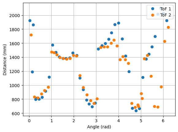
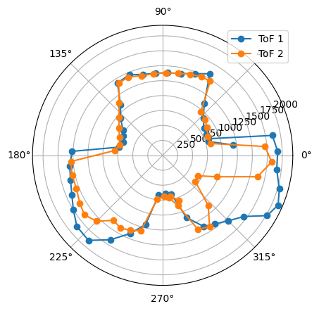
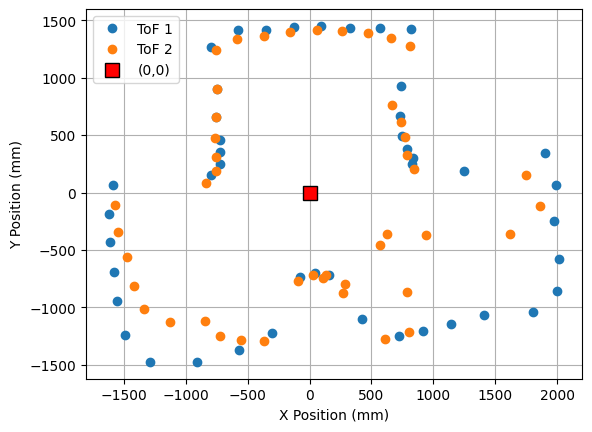
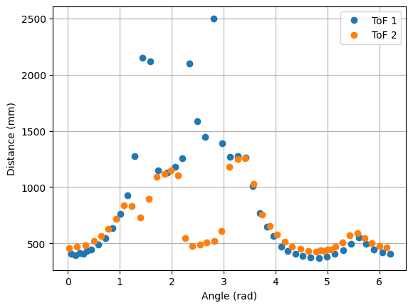
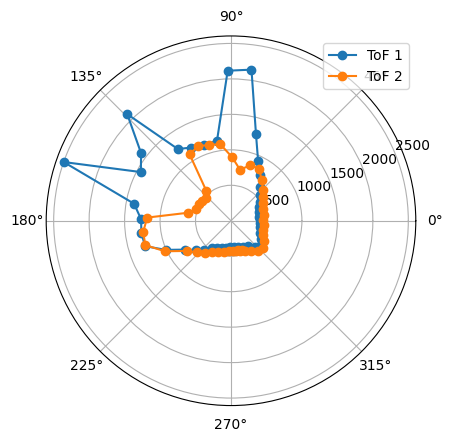
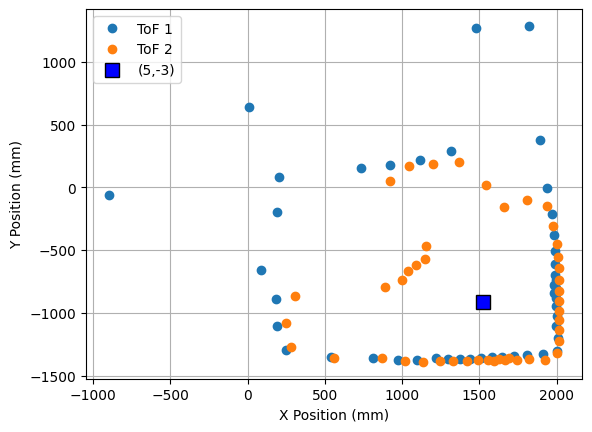
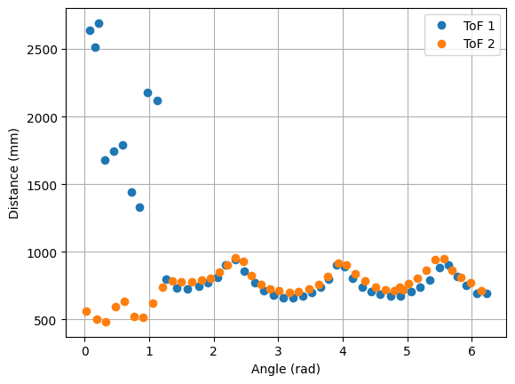
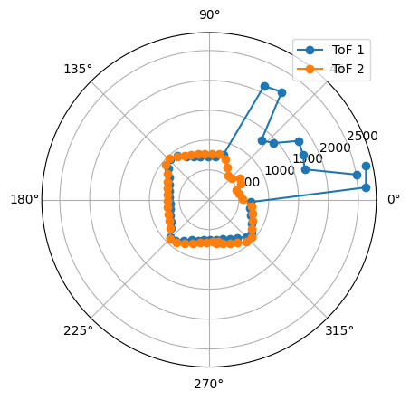
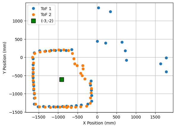
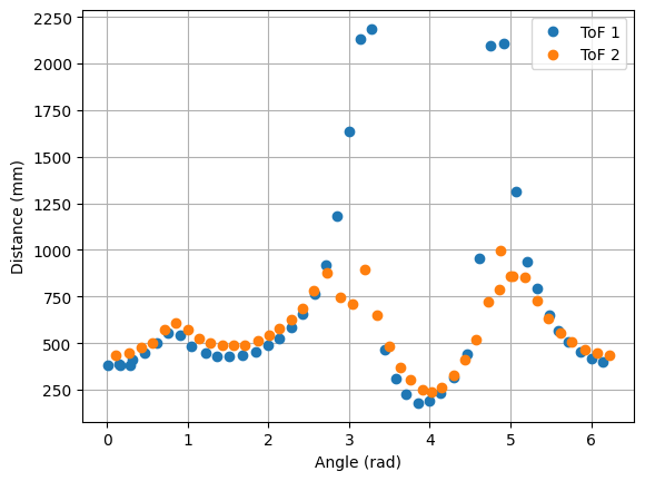
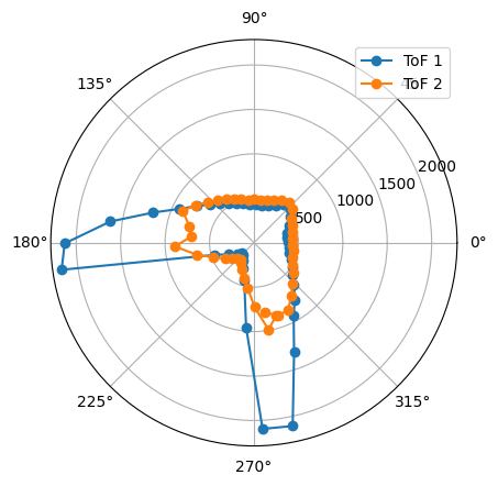
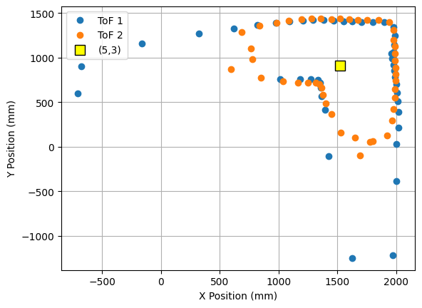
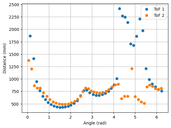
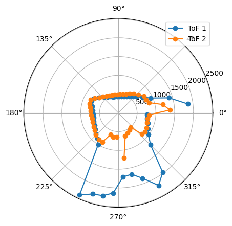
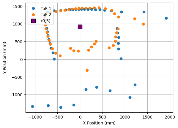
The robot was placed on each of the points in the floor, in order to map the room. For each point, 45 readings were taken, at 8 degrees of separation each (in total, a full 360 degree rotation). The controller parameters used were Kp = 8.5, Ki = 0.0, and Kd = 0.95. The result from each reading is shown below. The coordinates of each point are measured in feet, while the distances in the plots are in millimeters. For each point, three plots are provided: one which shows the ToF readings for every angle, a second one representing the readings in polar coordinates, and the last one representing the readings in the global map (after a transformation, explained in next section).
1. Point (0,0)
 |
 |
 |
2. Point (5,-3)
 |
 |
 |
3. Point (-3,-2)
 |
 |
 |
4. Point (5,3)
 |
 |
 |
5. Point (0,3)
 |
 |
 |
3. Transformation Matrices
The readings obtained from the tests above provide an angle and a distance for every turn. When reading, I considered the front ToF sensor to be pointing in the positive X direction, and the side one in the negative Y direction. I order to merge the readings and plot them together, we need to transform the points into the same reference system. We can do this with Transformation Matrices.
For every case, the reading is centered on the ToF sensor. Additionally, each reading is taken at a different angle, and from a different point in the map. Note that the angle for the side ToF sensor has been modified when sending the data by subtracting 90 degrees to the robot’s yaw, so it reflects the real angle for that reading. Therefore, for each readings we have:
- A point, where, if it was taken by the front ToF, the X distance is the ToF1 reading, and the Y distance is 0; or, if it was taken by the side ToF, the X distance is 0, and the Y distance is the negative ToF2 reading.
- Translation from the center of the robot to each ToF sensor. The front ToF sensor is 69.85mm from the center, in the X direction, while the side sensor is -34.925mm from the center, in the Y direction.
- Rotation on the robot’s axis. For every point, the robot has rotated a certain known angle. The transformation matrix in this case is:
- Translation from the center of the map (0,0), to the point $(P_X, P_Y)$ where we take the readings.
Therefore, to transform a reading into a point in the global map we need two translations and two rotations.
\[P_1^{global} = [T_{mat} \times (P_1+Tr_1)] + Translation\] \[P_2^{global} = [T_{mat}\times(P_2+Tr_2)] + Translation\]4. Global Map
After transforming every point to the global system of reference, we can obain the map of the room.
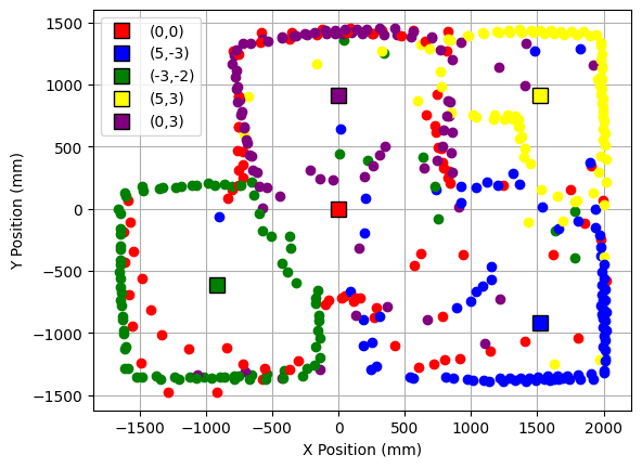
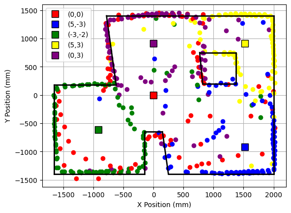
Last, the walls of the room were determined by hand, and then saved on a list with the start and ending coordinates of every wall. The list obtained is the following:
1
2
3
start = [[-1650, -1400], [-1650, 180], [-620, 180], [-780, 1400], [2000, 1400], [2000, -1400], [250, -1400], [150, -650], [-150, -650], [-150, -1400], [770, 750], [1370,750], [1370,200], [820,200]]

end = [[-1650, 180], [-620, 180], [-780, 1400], [2000, 1400], [2000, -1400], [250, -1400], [150, -650], [-150, -650], [-150, -1400], [-1650, -1400], [1370,750], [1370,200], [820,200], [770, 750]]
Last, the walls were plotted on top of the map, as shown below.
